« SE3 PSE Binome2023-6 » : différence entre les versions
Aller à la navigation
Aller à la recherche
(→PCB) |
|||
| Ligne 15 : | Ligne 15 : | ||
|- | |- | ||
|- | |- | ||
[[Fichier:ManetteVierge.jpg|400px|Une photo de la manette PCB sans aucun composants | | style="width:25%;" | [[Fichier:ManetteVierge.jpg|400px]] || style="width:25%;text-align:center;" | Une photo de la manette PCB sans aucun composants || style="width:25%;" | Visualisation 3D de la carte || style="width:25%;" | [[Fichier:Screenshot 2024-03-11 17-48-28.png|500px]] | ||
[[Fichier:Screenshot 2024-03-11 17- | |||
|- | |- | ||
|[[Fichier:Bootloader.jpg|400px]] || style="text-align:center;" | La manette en mode DFU, la petite LED en haut à droite allumée est dû au port connecté à cette LED. Les derniers ports PF (5,6,7) sont des PIN spéciaux qui allument les LED connectées | |||
|- | |- | ||
| [[Fichier:Screenshot 2024-03-11 17-47-48.png|400px]] || style="text-align:center;" | PCB final de la manette | |||
|- | |||
| [[Fichier:ManetteObsolète.jpg|400px]] || style="text-align:center;" | Première itération de soudage de la manette. Un court-circuit c'est créer lors de nos premiers soudages. La manette est devenue inutilisable par la suite, nous ne pouvions plus mettre le bootloader avec un Arduino sur l'ATMega | |||
|} | |} | ||
Version du 4 juin 2024 à 15:37
Conception de la manette
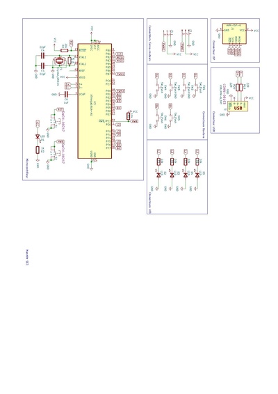
SCHÉMATIQUE KiCAD
 |
Screenshot de la schématique de l'ATMega | Screenshot de la schématique des connecteurs LEDs, Boutons, ISP et USB |

|
 |
PDF avec la schématique complète de la manette | 1ère Vidéo montrant l'interaction entre les boutons de la manette et l'application Joystick de l'ordinateur |
PCB
 |
Une photo de la manette PCB sans aucun composants | Visualisation 3D de la carte | 
|
 |
La manette en mode DFU, la petite LED en haut à droite allumée est dû au port connecté à cette LED. Les derniers ports PF (5,6,7) sont des PIN spéciaux qui allument les LED connectées | ||
 |
PCB final de la manette | ||
 |
Première itération de soudage de la manette. Un court-circuit c'est créer lors de nos premiers soudages. La manette est devenue inutilisable par la suite, nous ne pouvions plus mettre le bootloader avec un Arduino sur l'ATMega |
Code C

Pour pouvoir avoir nos boutons fonctionnel on s'est basé sur la démo du joystick pour créer "Manette", et ensuite on est partie d'un code minimal pour pouvoir rajouté la description de notre manette, et créer deux interfaces, une pour nos boutons, et une autre pour nos LEDs.
Minimal:

bool GetNextReport(USB_JoystickReport_Data_t* const ReportData)
{

	bool           InputChanged     = false;

	/* Clear the report contents */
	memset(ReportData, 0, sizeof(USB_JoystickReport_Data_t));

	if (~(PINF>>PIN7) & 1) ReportData->Button |= (1 << 1);
	if (~(PINF>>PIN6) & 1) ReportData->Button |= (1 << 0);
	if (~(PIND>>PIN1) & 1) ReportData->Y = 100;
	if (~(PIND>>PIN2) & 1) ReportData->X = 100;
	if (~(PIND>>PIN3) & 1) ReportData->X = -100;
	if (~(PIND>>PIN5) & 1) ReportData->Y = -100;


	InputChanged = 1;

	return InputChanged;
}
	/* Hardware Initialization */
	Joystick_Init();
	LEDs_Init();
	Buttons_Init();
	USB_Init();


	MCUCR |= (1<<JTD);
	MCUCR |= (1<<JTD);
	CLKSEL0 = 0b00010101;   // sélection de l'horloge externe
	CLKSEL1 = 0b00001111;   // minimum de 8Mhz
	CLKPR = 0b10000000;     // modification du diviseur d'horloge (CLKPCE=1)
	CLKPR = 0;              // 0 pour pas de diviseur (diviseur de 1)


	//Boutons A et B
	DDRF  &= 0b00111111;
	PORTF |= 0b11000000;

	//Boutons directionnels
	DDRD  &= 0b11010001;
	PORTD |= 0b00101110;


	// Allumer les leds
	PORTF |= 0b00100011;
	PORTE |= 0b01000000;
Montage de la carte :
Fichiers: Fichier:ManetteUSBLilianPierre.zip
gerber: Fichiers: Fichier:SE3-pad-job.gbrjob.zip gerber: Fichiers: Fichier:SE3-pad-LGPC.zip