« SE4Binome2024-5 » : différence entre les versions
Aller à la navigation
Aller à la recherche
| Ligne 38 : | Ligne 38 : | ||
} | } | ||
</syntaxhighlight> | |||
== Objectifs ordonnanceur 7 oct. == | |||
=== Allumer la LED broche PB5 avec Timer1 ISR == | |||
<syntaxhighlight lang="c" line> | |||
#define CTC1 WGM12 // Meilleur nom pour le bit | |||
#define PERIODE 20 | |||
void init_minuteur(int diviseur,long periode){ | |||
TCCR1A=0; // Le mode choisi n'utilise pas ce registre | |||
TCCR1B=(1<<CTC1); // Réinitialisation du minuteur sur expiration | |||
switch(diviseur){ | |||
case 8: TCCR1B |= (1<<CS11); break; | |||
case 64: TCCR1B |= (1<<CS11 | 11<<CS10); break; | |||
case 256: TCCR1B |= (1<<CS12); break; | |||
case 1024: TCCR1B |= (1<<CS12 | 1<<CS10); break; | |||
} | |||
// Un cycle prend 1/F_CPU secondes. | |||
// Un pas de compteur prend diviseur/F_CPU secondes. | |||
// Pour une periode en millisecondes, il faut (periode/1000)/(diviseur/F_CPU) pas | |||
// soit (periode*F_CPU)/(1000*diviseur) | |||
OCR1A=F_CPU/1000*periode/diviseur; // Calcul du pas | |||
TCNT1=0; // Compteur initialisé | |||
TIMSK1=(1<<OCIE1A); // Comparaison du compteur avec OCR1A | |||
} | |||
ISR(TIMER1_COMPA_vect/*, ISR_NAKED*/) // Procédure d'interruption | |||
{ | |||
PORTB ^= (1 << PB5); | |||
} | |||
int main(void){ | |||
DDRB |= (1 << PB5); | |||
init_minuteur(256,PERIODE); | |||
sei(); | |||
while(1); | |||
} | |||
</syntaxhighlight> | </syntaxhighlight> | ||
Version du 7 octobre 2024 à 09:11
git : https://gitea.plil.fr/ktouron/se4-djadja-touron_pico.git
Carte fille clavier "matrice de touches"
Hardware
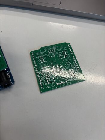
Reçu carte vierge
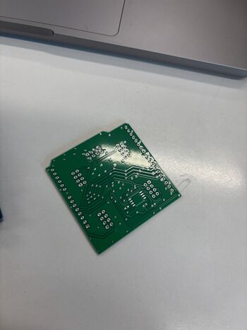
Carte après soudure des composants
Software
Allumage de LEDS sur Programmateur AVR
Avant de programmer directement sur le shield, nous avons allumé des LED pour tester la carte.
// the setup function runs once when you press reset or power the board
void setup() {
  // initialize digital pin LED_BUILTIN as an output.
  pinMode(LED_BUILTIN, OUTPUT);
}

// the loop function runs over and over again forever
void loop() {
  digitalWrite(1, HIGH);
  digitalWrite(4, HIGH);
  digitalWrite(7, HIGH);
  digitalWrite(A0, HIGH);
  digitalWrite(A3, HIGH);  // turn the LED on (HIGH is the voltage level)
  delay(1000);                      // wait for a second
  digitalWrite(1, LOW);
  digitalWrite(4, LOW);
  digitalWrite(7, LOW);
  digitalWrite(A0, LOW);
  digitalWrite(A3, LOW);   // turn the LED off by making the voltage LOW
  delay(1000);                      // wait for a second
}
Objectifs ordonnanceur 7 oct.
= Allumer la LED broche PB5 avec Timer1 ISR
#define CTC1            WGM12           // Meilleur nom pour le bit

#define PERIODE         20

void init_minuteur(int diviseur,long periode){
  TCCR1A=0;               // Le mode choisi n'utilise pas ce registre
  TCCR1B=(1<<CTC1);       // Réinitialisation du minuteur sur expiration
  switch(diviseur){
    case    8: TCCR1B |= (1<<CS11); break;
    case   64: TCCR1B |= (1<<CS11 | 11<<CS10); break;
    case  256: TCCR1B |= (1<<CS12); break;
    case 1024: TCCR1B |= (1<<CS12 | 1<<CS10); break;
    }
  // Un cycle prend 1/F_CPU secondes.
  // Un pas de compteur prend diviseur/F_CPU secondes.
  // Pour une periode en millisecondes, il faut (periode/1000)/(diviseur/F_CPU) pas
  // soit (periode*F_CPU)/(1000*diviseur)
  OCR1A=F_CPU/1000*periode/diviseur;  // Calcul du pas
  TCNT1=0;                // Compteur initialisé
  TIMSK1=(1<<OCIE1A);     // Comparaison du compteur avec OCR1A
}

ISR(TIMER1_COMPA_vect/*, ISR_NAKED*/)    // Procédure d'interruption
{
  PORTB ^= (1 << PB5);
}


int main(void){
  DDRB |= (1 << PB5);
  init_minuteur(256,PERIODE);
  sei();
  while(1);
}

