SE4Binome2024-3
Aller à la navigation
Aller à la recherche
Description
L'objectif de ce projet est de réaliser un pico ordinateur. Nous allons traiter le développement de la carte mère, un shield arduino ainsi que la programmation d'un ordonnanceur.
Notre carte mère sera alimenté via une alimentation secteur en 5v et le code sera implanté par USB.
Choix technologique
Pour alimenter les cartes filles, nous avons fait le choix de rendre disponible à la fois le 3v3 et le 5v. Pour ce faire nous allons utiliser des connecteurs HE -0 10 pins et non 8 pins dont voici les références :
-
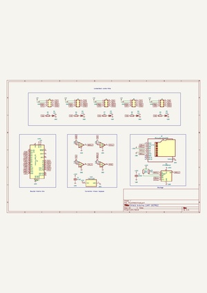
Réalisation d'un shield arduino
Schématique
Routage

PINOUT
| LED1 | PC0 |
| LED2 | PC3 |
| LED3 | PD1 |
| LED4 | PD4 |
| LED5 | PD7 |
Brasage du shield
shield nu

shield fini

Test du shield

Réalisation carte mère
Schématique
Routage
Programmation ordonnanceur
Code ordonnanceur
#include "Fonctions.h"

#define RESTORE_REGISTERS() \
asm volatile ( \
    "pop r31 \n\t" \
    "pop r30 \n\t" \
    "pop r29 \n\t" \
    "pop r28 \n\t" \
    "pop r27 \n\t" \
    "pop r26 \n\t" \
    "pop r25 \n\t" \
    "pop r24 \n\t" \
    "pop r23 \n\t" \
    "pop r22 \n\t" \
    "pop r21 \n\t" \
    "pop r20 \n\t" \
    "pop r19 \n\t" \
    "pop r18 \n\t" \
    "pop r17 \n\t" \
    "pop r16 \n\t" \
    "pop r15 \n\t" \
    "pop r14 \n\t" \
    "pop r13 \n\t" \
    "pop r12 \n\t" \
    "pop r11 \n\t" \
    "pop r10 \n\t" \
    "pop r9 \n\t" \
    "pop r8 \n\t" \
    "pop r7 \n\t" \
    "pop r6 \n\t" \
    "pop r5 \n\t" \
    "pop r4 \n\t" \
    "pop r3 \n\t" \
    "pop r2 \n\t" \
    "pop r1 \n\t" \
    "pop r0 \n\t" \
    "out __SREG__, r0 \n\t" \
    "pop r0 \n\t" \
);

#define SAVE_REGISTERS() \
asm volatile ( \
    "push r0 \n\t" \
    "in r0, __SREG__ \n\t" \
    "push r0 \n\t" \
    "push r1 \n\t" \
    "push r2 \n\t" \
    "push r3 \n\t" \
    "push r4 \n\t" \
    "push r5 \n\t" \
    "push r6 \n\t" \
    "push r7 \n\t" \
    "push r8 \n\t" \
    "push r9 \n\t" \
    "push r10 \n\t" \
    "push r11 \n\t" \
    "push r12 \n\t" \
    "push r13 \n\t" \
    "push r14 \n\t" \
    "push r15 \n\t" \
    "push r16 \n\t" \
    "push r17 \n\t" \
    "push r18 \n\t" \
    "push r19 \n\t" \
    "push r20 \n\t" \
    "push r21 \n\t" \
    "push r22 \n\t" \
    "push r23 \n\t" \
    "push r24 \n\t" \
    "push r25 \n\t" \
    "push r26 \n\t" \
    "push r27 \n\t" \
    "push r28 \n\t" \
    "push r29 \n\t" \
    "push r30 \n\t" \
    "push r31 \n\t" \
);

int currentTask = 0;
//uint16_t SP = 0x700;

// FONCTIONS

// Déclaration des différentes tâches
process task[NB_TASKS] = {
    {0x700,Serial_Led,0},
    {0x600, LED1_blink,0},
    {0x500, Serial_Message,0}
};

void init_pile(int N){
    uint16_t tempSP = SP;
    SP = task[N].stackPointer;
    uint16_t adresse=(uint16_t)task[N].addressFunction;
    asm volatile("push %0" : : "r" (adresse & 0x00ff) );
    asm volatile("push %0" : : "r" ((adresse & 0xff00)>>8) );
    SAVE_REGISTERS();
    task[N].stackPointer = SP;
    SP = tempSP;
}

void init_minuteur(int diviseur,long periode){
TCCR1A=0;               // Le mode choisi n'utilise pas ce registre
TCCR1B=(1<<CTC1);       // Réinitialisation du minuteur sur expiration
switch(diviseur){
  case    8: TCCR1B |= (1<<CS11); break;
  case   64: TCCR1B |= (1<<CS11 | 11<<CS10); break;
  case  256: TCCR1B |= (1<<CS12); break;
  case 1024: TCCR1B |= (1<<CS12 | 1<<CS10); break;
  }
// Un cycle prend 1/F_CPU secondes.
// Un pas de compteur prend diviseur/F_CPU secondes.
// Pour une periode en millisecondes, il faut (periode/1000)/(diviseur/F_CPU) pas
// soit (periode*F_CPU)/(1000*diviseur)
OCR1A=F_CPU/1000*periode/diviseur;  // Calcul du pas
TCNT1=0;                // Compteur initialisé
TIMSK1=(1<<OCIE1A);     // Comparaison du compteur avec OCR1A
}

void scheduler(){
    currentTask ++;
    if(currentTask == NB_TASKS) currentTask = 0; // ordonnanceur en mode Round Robin
}

// Déclaration d'un tableau de processus
ISR(TIMER1_COMPA_vect, ISR_NAKED){    // Procédure d'interruption
/* Sauvegarde du contexte de la tâche interrompue */
SAVE_REGISTERS();
task[currentTask].stackPointer = SP;
/* Appel à l'ordonnanceur */
scheduler();
/* Récupération du contexte de la tâche ré-activée */
SP = task[currentTask].stackPointer;
RESTORE_REGISTERS();
asm volatile ( "reti" );
}

int main(void){
cli();
LED_init();
USART_Init(MYUBRR);
init_minuteur(256,PERIODE);
for(int i=1;i<NB_TASKS;i++) init_pile(i);
SP = task[0].stackPointer;
sei();
task[0].addressFunction();
}
Code des tâches
#ifndef FONCTIONS_H
#define FONCTIONS_H

// Inclusions de bibliothèques nécessaires
#include <avr/io.h>
#include <avr/interrupt.h>
#include <stdint.h>
#include <util/delay.h>

#define CTC1            WGM12           // Meilleur nom pour le bit

#define PERIODE         20
#define FOSC 16000000 // Clock Speed
#define BAUD 9600
#define MYUBRR FOSC/16/BAUD-1

#define LED1 PC0
#define LED2 PC3
#define LED3 PD1
#define LED4 PD4
#define LED5 PD7

#define NB_TASKS 3

typedef struct process{
    uint16_t stackPointer; // stack pointer, défini le début du process
    void (*addressFunction)(void); // adresse de l'instruction en cours
    int state; // état de la fonction (prêt, en cours, terminé)
}process;

void LED_init(void);
void USART_Init(unsigned int ubrr);
void LED1_blink(void);
void LED2_blink(void);
void LED3_blink(void);
void LED4_blink(void);
void LED5_blink(void);
void USART_Transmit(unsigned char data);
unsigned char USART_Receive(void);
void Serial_Led();
void Serial_Message();

#endif
#include "Fonctions.h"

void LED_init(){
    DDRC |= (1<<LED1) | (1<<LED2);
    DDRD |= (1<<LED3) | (1<<LED4) | (1<<LED5);
    PORTC |= (1<<LED1)|(1<<LED2);
    PORTD |= (1<<LED3)|(1<<LED4)|(1<<LED5);
}

void USART_Init(unsigned int ubrr)
{
/*Set baud rate */
UBRR0H = (unsigned char)(ubrr>>8);
UBRR0L = (unsigned char)ubrr;
/*Enable receiver and transmitter */
UCSR0B = (1<<RXEN0)|(1<<TXEN0);
/* Set frame format: 8data, 2stop bit */
UCSR0C = (1<<USBS0)|(3<<UCSZ00);
}

void LED1_blink(){
    while(1){
        PORTC ^= (1<<LED1);
        _delay_ms(150);
    }
}

void LED2_blink(){
    while(1){
        PORTC ^= (1<<LED2);
        _delay_ms(100);
    }
}

void LED3_blink(){
    while(1){
        PORTD ^= (1<<LED3);
        _delay_ms(250);
    }
}

void LED4_blink(){
    while(1){
        PORTD ^= (1<<LED4);
        _delay_ms(350);
    }
}

void LED5_blink(){
    while(1){
        PORTD ^= (1<<LED5);
        _delay_ms(50);
    }
}

void Serial_Led(){
    while(1){
        if(USART_Receive() == 'a') LED2_blink();

    }
}

void Serial_Message(){
    unsigned char data;
    while(1){
         data = USART_Receive();
        USART_Transmit(data);
    }
}

void USART_Transmit(unsigned char data)
{
/* Wait for empty transmit buffer */
while (!(UCSR0A & (1<<UDRE0)))
;
/* Put data into buffer, sends the data */
UDR0 = data;
}

unsigned char USART_Receive(void)
{
/* Wait for data to be received */
while (!(UCSR0A & (1<<RXC0)))
;
/* Get and return received data from buffer */
return UDR0;
}
Exemple d'utilisation
Clignotement de 5 Leds asynchrones
Affichage clavier avec minicom
Liens
Lien du git : https://gitea.plil.fr/vdetrez/SE4_PICO_DETREZ_CART