SE3 PSE Binome2023-4
Notre manette
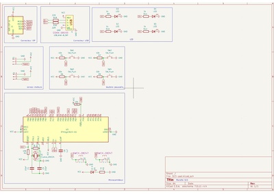
Dans ce module nous allons modéliser une carte PCB sur le logiciel Kicad pour réaliser une manette constitué de 4 boutons poussoirs ainsi que 4 LED.
projet git : https://archives.plil.fr/yyahiani/Yassine_Bilal_1SE.git
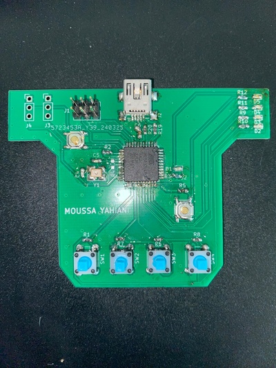
Voici une photo de la carte soudée :
Vous trouverez ci-dessous les fichier de notre projets témoignant de notre avancement:
Projet KiCAD : Fichier:SE3pad.zip
Fichier Gerber : Fichier:Gerber.zip
Programateur AVR
CODE CLIGNOTEMENT
#include <avr/io.h>
#include <util/delay.h>
#include <stdio.h>
int main(void) {
CLKSEL0 = 0b00010101; // sélection de l'horloge externe
CLKSEL1 = 0b00001111; // minimum de 8Mhz
CLKPR = 0b10000000; // modification du diviseur d'horloge (CLKPCE=1)
CLKPR = 0;
// Configuration des broches PD1 et PD2 comme sorties
DDRD |= (1 << PD1) | (1 << PD2);
while (1) {
// Allumer la LED connectée à PD1
PORTD |= (1 << PD1);
_delay_ms(500); // Attendre 500 millisecondes
// Éteindre la LED connectée à PD1 et allumer la LED connectée à PD2
PORTD &= ~(1 << PD1);
PORTD |= (1 << PD2);
_delay_ms(500); // Attendre 500 millisecondes
// Éteindre la LED connectée à PD2
PORTD &= ~(1 << PD2);
_delay_ms(500); // Attendre 500 millisecondes
}CODE CLIGNOTEMENT
return 0;
}
MAKEFILE:
export CC = avr-gcc
export MCU = atmega8u2
export TARGET_ARCH = -mmcu=$(MCU)
export CFLAGS = -Wall -I. -DF_CPU=16000000 -Os #-g
export LDFLAGS = -g $(TARGET_ARCH) -lm -Wl,--gc-sections # -Os
TARGET = projet
TERM = /dev/ttyACM0
CPPFLAGS = -mmcu=$(MCU)
PGMER = -c stk500v1 -b 115200 -P $(TERM)
export DUDE = /usr/bin/avrdude -F -v -p $(MCU)
C_SRC = $(wildcard *.c)
OBJS = $(C_SRC:.c=.o)
all: $(TARGET).hex
clean:
rm -f *.o
%.o:%.c
$(CC) -c $(CPPFLAGS) $(CFLAGS) $< -o $@
$(TARGET).elf: $(OBJS)
$(CC) $(LDFLAGS) -o $@ $(OBJS)
$(TARGET).hex: $(TARGET).elf
avr-objcopy -j .text -j .data -O ihex $(TARGET).elf $(TARGET).hex
upload: $(TARGET).hex
stty -F $(TERM) hupcl # reset
$(DUDE) $(PGMER) -U flash:w:$(TARGET).hex
size: $(TARGET).elf
avr-size --format=avr --mcu=$(MCU) $(TARGET).elf