SE3 PSE Binome2023-4
Notre manette
Introduction
Le projet que nous présentons ici vise à concevoir et réaliser une manette de jeu personnalisée, intégrant des composants électroniques simples et des techniques de programmation avancées. À travers ce projet, nous avons cherché à combiner l'apprentissage de la conception de circuits imprimés (PCB) avec le logiciel KiCad, la soudure des composants électroniques, ainsi que la programmation d'un microcontrôleur AVR pour faire fonctionner la manette.
Notre objectif principal était de créer une manette dotée de quatre boutons poussoirs et de quatre LED, toutes intégrées sur une carte électronique. Nous avons choisi KiCad pour sa flexibilité et ses outils puissants de conception de schémas et de routage de PCB. La programmation du microcontrôleur a été réalisée en utilisant des outils comme LUFA et LIBUSB, permettant ainsi la communication USB entre la manette et un ordinateur.
Conception
Conception Kicad
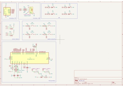
Premièrement, nous devons modéliser le schéma de notre carte PCB, pour cela nous avons fait le choix du logiciel dit Kicad pour sa simplicité et son efficacité mise en avant par les enseignants.
Nous nous somme inspiré de différents schéma déjà existant que les enseignants nous on fournit ainsi que nos propres recherches pour modéliser notre cartes et y intégré tout les éléments spécifique à notre projets, voici donc le schéma final de notre carte:
Une fois la schématique de notre manette validée par les enseignants, nous passons au routage de notre système, le routage consiste à préparer la fabrication de notre carte et lui donner l'allure souhaité en agençant minutieusement chaque composant et chaque fil de cuivre les reliant les un aux autres, voici notre routage complet et validé par nos enseignants:

Nous avons par la suite générer les fichiers de production que vous pourrez retrouver dans notre dépôt git (fichier gerber).
Soudure
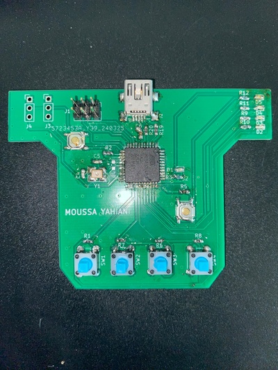
Une fois la carte sortie de fabrication et reçu en salle, l'heure est à la soudure de nos composants sur notre PCB, pour être rigoureux chaque composant, après avoir été soudé, doit être testé avec un multimètre pour vérifier la continuité à travers notre circuit.
Voici une photo de la carte soudée :
Programmation
Programmateur AVR
Nous pouvons dès à présent attaquer la partie programmation, nous allons tester nos LED en codant un simple code permettant de les faire clignoter, nous allons utiliser un programmateur AVR (à défaut d'avoir bootloader la carte pour l'instant) pour programmer pour µC et exécuter le code
voici le code en question:
#include <stdio.h>
#include <avr/io.h>
#include <util/delay.h>

#define F_CPU 8000000UL // Définition de la fréquence du microcontrôleur (8 MHz)

int main(void) {
    CLKSEL0 = 0b00010101;   // sélection de l'horloge externe
    CLKSEL1 = 0b00001111;   // minimum de 8Mhz
    CLKPR = 0b10000000;     // modification du diviseur d'horloge (CLKPCE=1)
    CLKPR = 0;              // 0 pour pas de diviseur (diviseur de 1)

    // Configuration des broches PD1 et PD2 comme sorties
    DDRD |= (1 << PD1) | (1 << PD2);

    while (1) {
        // Allumer la LED connectée à PD1
        PORTD |= (1 << PD1);
        _delay_ms(500); // Attendre 500 millisecondes

        // Éteindre la LED connectée à PD1 et allumer la LED connectée à PD2
        PORTD &= ~(1 << PD1);
        PORTD |= (1 << PD2);
        _delay_ms(500); // Attendre 500 millisecondes

        // Éteindre la LED connectée à PD2
        PORTD &= ~(1 << PD2);
        _delay_ms(500); // Attendre 500 millisecondes
    }

    return 0;
}
ainsi que le Makefile fournit par notre enseignant:
export CC = avr-gcc

export MCU = atmega8u2
export TARGET_ARCH = -mmcu=$(MCU)

export CFLAGS =  -Wall -I. -DF_CPU=16000000 -Os #-g
export LDFLAGS = -g $(TARGET_ARCH) -lm -Wl,--gc-sections #	-Os


TARGET = AVR_prog
TERM = /dev/ttyUSB0
#TERM = /dev/ttyACM0
CPPFLAGS = -mmcu=$(MCU)
PGMER = -c stk500v1 -b 57600 -P $(TERM)
PGMERISP = -c stk500v1 -b 115200 -P $(TERM)
ARVDUDECONF= -C /usr/local/arduino/arduino-0021/hardware/tools/avrdude.conf
export DUDE = /usr/bin/avrdude -F -v -p $(MCU) $(AVRDUDECONF)

C_SRC = $(wildcard *.c)
OBJS = $(C_SRC:.c=.o)


all: $(TARGET).hex

ass:$(C_SRC)
	$(CC) -S $(CPPFLAGS) $(CFLAGS) $< -o $@

clean:
	rm -f *.o

%.o:%.c
	$(CC) -c $(CPPFLAGS) $(CFLAGS) $< -o $@


$(TARGET).elf: $(OBJS)
	$(CC) $(LDFLAGS) -o $@ $(OBJS)

$(TARGET).hex: $(TARGET).elf
	avr-objcopy -j .text -j .data -O ihex $(TARGET).elf $(TARGET).hex

upload: $(TARGET).hex
	stty -F $(TERM) hupcl # reset
	$(DUDE) $(PGMER) -U flash:w:$(TARGET).hex
#	$(DUDE) $(PGMERISP) -U flash:w:$(TARGET).hex

size: $(TARGET).elf
	avr-size --format=avr --mcu=$(MCU) $(TARGET).elf
Programmation µC
Programmation via ISP
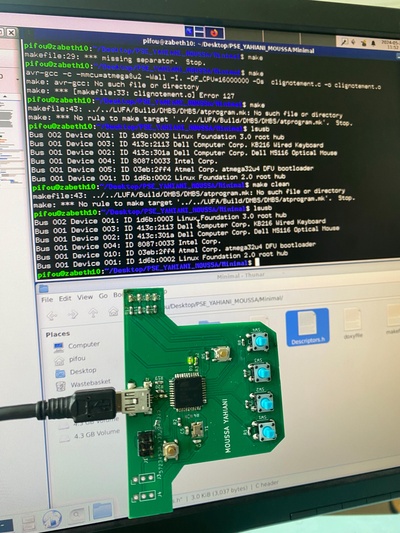
Lors de l'exécution de la commande "lsusb" dans le terminal, notre µC n'est pas détecté par l'ordinateur, nous devons donc bootloader notre carte en la connectant via l'ISP à un Arduino que l'enseignant possède et exécuter cette commande dans le terminal:
avrdude -c stk500v1 -p atmega32u4 -P /dev/ttyACM0 -b 19200 -U lfuse:w:0xFF:m -U efuse:w:0xF7:m
Après avoir bootloader notre µC via l'ISP, notre manette est reconnaissable par l'ordinateur et prête à l'emploi et l'AtMega passera en mode DFU lors de la pression des boutons HWB et Reset simultanément, nous avons utiliser la commande "lsusb" dans le terminal pour voir si l'ordinateur détectait notre manette lorsque nous la branchons via USB:
Test des LED
Nous pouvons d'ores et déjà tester notre carte sans passer par un programmateur AVR, en compilant et flashant directement le code sur notre manette, il s'exécutera automatiquement lors de la mise en tension de notre carte, voici le code:
#include<avr/io.h> #include<stdio.h>
#include<util/delay.h>
int main (void)
MCUCR |= (1<<JTD) ;
MCUCR |= (1<<JTD) ;
DDRF = 0XFF;
while (1)
{
PORTF = 0x20;
delay_ms (1000) ;
PORTF = 0x10;
_delay_ms (1000) ;
머
return 0;
}
Nous utilisons le Makefile suivant:
export CC = avr-gcc

export MCU = atmega32u4
export TARGET_ARCH = -mmcu=$(MCU)

export CFLAGS =  -Wall -I. -DF_CPU=16000000 -Os #-g
export LDFLAGS = -g $(TARGET_ARCH) -lm -Wl,--gc-sections #	-Os


TARGET = AVR_prog
TERM = /dev/ttyUSB0
#TERM = /dev/ttyACM0
CPPFLAGS = -mmcu=$(MCU)
PGMER = -c stk500v1 -b 57600 -P $(TERM)
PGMERISP = -c stk500v1 -b 115200 -P $(TERM)
ARVDUDECONF= -C /usr/local/arduino/arduino-0021/hardware/tools/avrdude.conf
export DUDE = /usr/bin/avrdude -F -v -p $(MCU) $(AVRDUDECONF)

C_SRC = $(wildcard *.c)
OBJS = $(C_SRC:.c=.o)


all: $(TARGET).hex

ass:$(C_SRC)
	$(CC) -S $(CPPFLAGS) $(CFLAGS) $< -o $@

clean:
	rm -f *.o *.elf *.hex

%.o:%.c
	$(CC) -c $(CPPFLAGS) $(CFLAGS) $< -o $@


$(TARGET).elf: $(OBJS)
	$(CC) $(LDFLAGS) -o $@ $(OBJS)

$(TARGET).hex: $(TARGET).elf
	avr-objcopy -j .text -j .data -O ihex $(TARGET).elf $(TARGET).hex

upload: $(TARGET).hex
	stty -F $(TERM) hupcl # reset
	$(DUDE) $(PGMER) -U flash:w:$(TARGET).hex

size: $(TARGET).elf
	avr-size --format=avr --mcu=$(MCU) $(TARGET).elf

# Ajout des cibles spécifiques pour effacer, démarrer et flasher
start:
	$(DUDE) $(PGMER) -U flash:w:$(TARGET).hex

erase:
	$(DUDE) $(PGMER) -e

flash: erase $(TARGET).hex
	$(DUDE) $(PGMER) -U flash:w:$(TARGET).hex

.PHONY: clean start erase flash upload size
LUFA & LIBSUB
Nous avons télécharger les bibliothèque LUFA et LIBSUB pour en extraire les code spécifique à la programmation des joystick pour que nos joystick soient prit en compte par la machine, ainsi que le minimal nous permettant d'envoyer des bits de donnée aux LED et pouvoirs les contrôler à notre guise, pour finir nos génèrerons le merge entre les joystick et les LED pour pouvoir les utiliser en même temps dans notre jeu Space Invaders
Joystick
Nous avons modifier le code "Joystick.c" present dans la bibliothèque LUFA pour initialiser nos boutons:
MCUCR |= (1<<JTD);
  MCUCR |= (1<<JTD);

  DDRB &= ~0b00110000;
  PORTB |= 0b00110000;

  DDRD &= ~0b11010000;
  PORTD |= 0b11010000;

  DDRF &= ~0b11000000;
  PORTF |= 0b11000000;
Nous testerons ensuite les joystick un à la fois:
bool GetNextReport(USB_JoystickReport_Data_t* const ReportData)
{
  static uint8_t PrevJoyStatus    = 0;
  static uint8_t PrevButtonStatus = 0;
  bool           InputChanged     = false;

  /* Clear the report contents */
  memset(ReportData, 0, sizeof(USB_JoystickReport_Data_t));

  if(~(PIND>>PD4) & 1){
    ReportData->X = -100;
  }
  if(~(PIND>>PD7) & 1){
    ReportData->X =  100;
  }
  if(~(PIND>>PD6) & 1){
    ReportData->Y = -100;
  }
  if(~(PINB>>PB4) & 1){
    ReportData->Y =  100;
  }
  if(~(PINF>>PF7) & 1){
    ReportData->Button |= (1 << 0);
  }
  if(~(PINF>>PF6) & 1){
    ReportData->Button |= (1 << 1);
  }
  /* Return whether the new report is different to the previous report or not */
  return InputChanged;
}
Voici maintenant nos joystick prêt à l'utilisation, bien entendu l'entièreté des codes ce trouve dans notre dépôt GIT, passons maintenant à la configuration des LED.
LED
Toujours dans le même principe, nous modifions le code minimal.c présent pour les LED afin de les adapter à nos besoins en intégrant cela à notre code:
MCUCR |= (1<<JTD);
MCUCR |= (1<<JTD);
DDRF |= 0b00110011;

DDRD &= ~0b11010000;
PORTD |= 0b11010000;
Vous trouverez la totalité des code modifié dans notre dépôt GIT, y comprit l'adaptation de Descriptors.c et Descriptors.h
Merge
Pour que nos joystick et nos LED soient fonctionnelle de manière simultané, nous devons les fusionner dans un seul fichier.c et bien sur adapter le fichier .h, voici le fichier .c fusionnant l'initialisation des LED et des joystick:
/*
  LUFA Library
  Copyright (C) Dean Camera, 2021.

  dean [at] fourwalledcubicle [dot] com
  www.lufa-lib.org
*/

/*
  Copyright 2021  Dean Camera (dean [at] fourwalledcubicle [dot] com)

  Permission to use, copy, modify, distribute, and sell this
  software and its documentation for any purpose is hereby granted
  without fee, provided that the above copyright notice appear in
  all copies and that both that the copyright notice and this
  permission notice and warranty disclaimer appear in supporting
  documentation, and that the name of the author not be used in
  advertising or publicity pertaining to distribution of the
  software without specific, written prior permission.

  The author disclaims all warranties with regard to this
  software, including all implied warranties of merchantability
  and fitness.  In no event shall the author be liable for any
  special, indirect or consequential damages or any damages
  whatsoever resulting from loss of use, data or profits, whether
  in an action of contract, negligence or other tortious action,
  arising out of or in connection with the use or performance of
  this software.
*/

/** \file
 *
 *  Main source file for the Joystick demo. This file contains the main tasks of the demo and
 *  is responsible for the initial application hardware configuration.
 */

#include "Manette.h"

/** Main program entry point. This routine configures the hardware required by the application, then
 *  enters a loop to run the application tasks in sequence.
 */
int main(void)
{
  SetupHardware();

  //LEDs_SetAllLEDs(LEDMASK_USB_NOTREADY);
  GlobalInterruptEnable();

  for (;;)
    {
      HID_Task();
      EVENT_USB_OutPoint();
      USB_USBTask();
    }
}

/** Configures the board hardware and chip peripherals for the demo's functionality. */
void SetupHardware(void)
{
#if (ARCH == ARCH_AVR8)
  /* Disable watchdog if enabled by bootloader/fuses */
  MCUSR &= ~(1 << WDRF);
  wdt_disable();

  /* Disable clock division */
  clock_prescale_set(clock_div_1);
#elif (ARCH == ARCH_XMEGA)
  /* Start the PLL to multiply the 2MHz RC oscillator to 32MHz and switch the CPU core to run from it */
  XMEGACLK_StartPLL(CLOCK_SRC_INT_RC2MHZ, 2000000, F_CPU);
  XMEGACLK_SetCPUClockSource(CLOCK_SRC_PLL);

  /* Start the 32MHz internal RC oscillator and start the DFLL to increase it to 48MHz using the USB SOF as a reference */
  XMEGACLK_StartInternalOscillator(CLOCK_SRC_INT_RC32MHZ);
  XMEGACLK_StartDFLL(CLOCK_SRC_INT_RC32MHZ, DFLL_REF_INT_USBSOF, F_USB);

  PMIC.CTRL = PMIC_LOLVLEN_bm | PMIC_MEDLVLEN_bm | PMIC_HILVLEN_bm;
#endif

  MCUCR |= (1<<JTD);
  MCUCR |= (1<<JTD);

  DDRB &= ~0b00110000;
  PORTB |= 0b00110000;

  DDRD &= ~0b11010000;
  PORTD |= 0b11010000;

  DDRF &= ~0b11000000;
  PORTF |= 0b11000000;

 DDRF |= 0b00110011;

  DDRD &= ~0b11010000;
  PORTD |= 0b11010000;
  /* Hardware Initialization */
  Joystick_Init();
  LEDs_Init();
  Buttons_Init();
  USB_Init();
}

/** Event handler for the USB_Connect event. This indicates that the device is enumerating via the status LEDs and
 *  starts the library USB task to begin the enumeration and USB management process.
 */
void blink_leds(void){
  PORTF |= 0b00110011;
  _delay_ms(200);
  PORTF &= ~0b00110011;
  _delay_ms(200);
  PORTF |= 0b00110011;
  _delay_ms(200);
  PORTF &= ~0b00110011;
}

void EVENT_USB_Device_Connect(void)
{
  /* Indicate USB enumerating */
  //LEDs_SetAllLEDs(LEDMASK_USB_ENUMERATING);
}

/** Event handler for the USB_Disconnect event. This indicates that the device is no longer connected to a host via
 *  the status LEDs and stops the USB management and joystick reporting tasks.
 */
void EVENT_USB_Device_Disconnect(void)
{
  /* Indicate USB not ready */
  //LEDs_SetAllLEDs(LEDMASK_USB_NOTREADY);
  blink_leds();
}

/** Event handler for the USB_ConfigurationChanged event. This is fired when the host set the current configuration
 *  of the USB device after enumeration - the device endpoints are configured and the joystick reporting task started.
 */
void EVENT_USB_Device_ConfigurationChanged(void)
{
  bool ConfigSuccess = true;

  /* Setup HID Report Endpoint */
  ConfigSuccess &= Endpoint_ConfigureEndpoint(JOYSTICK_EPADDR, EP_TYPE_INTERRUPT, JOYSTICK_EPSIZE, 1);
  Endpoint_ConfigureEndpoint(POINTIN_ADDR , EP_TYPE_INTERRUPT, ENDPOINT_SIZE, 1);
  Endpoint_ConfigureEndpoint(POINTOUT_ADDR , EP_TYPE_INTERRUPT, ENDPOINT_SIZE, 1);

  /* Indicate endpoint configuration success or failure */
  //LEDs_SetAllLEDs(ConfigSuccess ? LEDMASK_USB_READY : LEDMASK_USB_ERROR);
}

/** Event handler for the USB_ControlRequest event. This is used to catch and process control requests sent to
 *  the device from the USB host before passing along unhandled control requests to the library for processing
 *  internally.
 */
void EVENT_USB_Device_ControlRequest(void)
{
  /* Handle HID Class specific requests */
  switch (USB_ControlRequest.bRequest)
    {
    case HID_REQ_GetReport:
      if (USB_ControlRequest.bmRequestType == (REQDIR_DEVICETOHOST | REQTYPE_CLASS | REQREC_INTERFACE))
	{
	  USB_JoystickReport_Data_t JoystickReportData;

	  /* Create the next HID report to send to the host */
	  GetNextReport(&JoystickReportData);

	  Endpoint_ClearSETUP();

	  /* Write the report data to the control endpoint */
	  Endpoint_Write_Control_Stream_LE(&JoystickReportData, sizeof(JoystickReportData));
	  Endpoint_ClearOUT();
	}

      break;
    }
}

void EVENT_USB_InPoint(void)
{
  /* Select the IN Endpoint */
  Endpoint_SelectEndpoint(POINTIN_ADDR);
  /* Check if Endpoint Ready for Read/Write */
  if(Endpoint_IsReadWriteAllowed()){
    /* Write Keyboard Report Data */
    //Endpoint_Write_xxx(...);
    /* Finalize the stream transfer to send the last packet */
    Endpoint_ClearIN();
  }
}

void EVENT_USB_OutPoint(void)
{
  /* Select the OUT Endpoint */
  Endpoint_SelectEndpoint(POINTOUT_ADDR);
  /* Check if Endpoint contains a packet */
  //if(Endpoint_IsOUTReceived()){
    /* Check to see if the packet contains data */
   //if(Endpoint_IsReadWriteAllowed()){
      /* Read from the host */
      uint8_t o;
      o = Endpoint_Read_8();

      /* Process the data from the host */

      //Led D1
      if(o == 0x01){
        PORTF |= (1<<PF0);
      }
      if(o == 0x11){
        PORTF &= ~(1<<PF0);
      }

      //Led D2
      if(o == 0x02){
        PORTF |= (1<<PF1);
      }
      if(o == 0x12){
        PORTF &= ~(1<<PF1);
      }

      //Led D3
      if(o == 0x03){
        PORTF |= (1<<PF4);
      }
      if(o == 0x13){
        PORTF &= ~(1<<PF4);
      }

      //Led D4
      if(o == 0x04){
        PORTF |= (1<<PF5);
      }
      if(o == 0x14){
        PORTF &= ~(1<<PF5);
      }
  //  }
    /* Handshake the OUT Endpoint - clear endpoint and ready for next report */
    Endpoint_ClearOUT();
  //}
}

/** Fills the given HID report data structure with the next HID report to send to the host.
 *
 *  \param[out] ReportData  Pointer to a HID report data structure to be filled
 *
 *  \return Boolean \c true if the new report differs from the last report, \c false otherwise
 */
bool GetNextReport(USB_JoystickReport_Data_t* const ReportData)
{
  static uint8_t PrevJoyStatus    = 0;
  static uint8_t PrevButtonStatus = 0;
  bool           InputChanged     = false;

  /* Clear the report contents */
  memset(ReportData, 0, sizeof(USB_JoystickReport_Data_t));

  if(~(PIND>>PD4) & 1){
    ReportData->X = -100;
  }
  if(~(PIND>>PD7) & 1){
    ReportData->X =  100;
  }
  if(~(PIND>>PD6) & 1){
    ReportData->Y = -100;
  }
  if(~(PINB>>PB4) & 1){
    ReportData->Y =  100;
  }
  if(~(PINF>>PF7) & 1){
    ReportData->Button |= (1 << 0);
  }
  if(~(PINF>>PF6) & 1){
    ReportData->Button |= (1 << 1);
  }
  /* Return whether the new report is different to the previous report or not */
  return InputChanged;
}

/** Function to manage HID report generation and transmission to the host. */
void HID_Task(void)
{
  /* Device must be connected and configured for the task to run */
  if (USB_DeviceState != DEVICE_STATE_Configured)
    return;

  /* Select the Joystick Report Endpoint */
  Endpoint_SelectEndpoint(JOYSTICK_EPADDR);

  /* Check to see if the host is ready for another packet */
  if (Endpoint_IsINReady())
    {
      USB_JoystickReport_Data_t JoystickReportData;

      /* Create the next HID report to send to the host */
      GetNextReport(&JoystickReportData);

      /* Write Joystick Report Data */
      Endpoint_Write_Stream_LE(&JoystickReportData, sizeof(JoystickReportData), NULL);

      /* Finalize the stream transfer to send the last packet */
      Endpoint_ClearIN();

      /* Clear the report data afterwards */
      memset(&JoystickReportData, 0, sizeof(JoystickReportData));
    }
}
Conclusion
Dans l'ensemble, notre projet de conception et réalisation d'une manette de jeu personnalisée a été une expérience enrichissante. Nous avons pu combiner des compétences en conception de circuits imprimés, soudure électronique et programmation de microcontrôleurs pour créer un produit fonctionnel et amusant.
Grâce à l'utilisation de logiciels comme KiCad pour la conception de PCB et AVR-GCC pour la programmation des microcontrôleurs, nous avons pu concrétiser notre vision de la manette. Nous avons également appris à utiliser des outils de développement tels que LUFA et LIBUSB pour adapter les fonctionnalités de la bibliothèque standard à nos besoins spécifiques.
Enfin, grâce à une collaboration étroite avec nos enseignants et à un travail d'équipe efficace, nous avons pu surmonter les obstacles et atteindre nos objectifs. Nous sommes fiers du travail accompli et des compétences que nous avons acquises tout au long du processus.
Nous espérons que notre manette apportera de la joie et de l'amusement à ceux qui auront la chance de l'utiliser, et nous sommes impatients de poursuivre notre apprentissage et nos projets futurs dans le domaine de l'électronique et de la programmation.
Pour en conclure, nos joystick et nos LED peuvent être utilisé à notre guise dans notre jeu space invader après fusion, vous pourrez retrouver ce fichier nommé Manette dans notre dépôt GIT prêt à compiler et interagir dans notre jeu.
Malheureusement, à défaut de posséder la manette on ne pourra pas vous proposer de démonstration vidéo de la manette interagissant avec notre jeu Space Invaders, cependant tout les éléments théoriques sont présent pour mettre en place une manette prête à l'utilisation et répondant à nos besoin.
GIT
projet git : https://archives.plil.fr/yyahiani/Yassine_Bilal_PSE.git