SE4Binome2024-7
Aller à la navigation
Aller à la recherche
Code Source et autre programmes
Ordonnanceur
INCLUDE & VARIABLES
#include <avr/io.h>
#include <util/delay.h>
#include <avr/interrupt.h>
#include "ordonnanceur1.h"

#define CTC1            WGM12
#define PERIODE         20
#define NB_TASKS 2
int currentTask = 0;

Task TaskList[NB_TASKS]={
  {task_led1, 0x600, 1},
  {task_led2, 0x700, 1}
};
Initialisation du minuteur et PRESCALER
void init_minuteur(int diviseur,long periode)
{
  TCCR1A=0;               // Le mode choisi n'utilise pas ce registre
  TCCR1B=(1<<CTC1);       // Réinitialisation du minuteur sur expiration
  switch(diviseur)
  {
    case    8: TCCR1B |= (1<<CS11); break;
    case   64: TCCR1B |= (1<<CS11 | 11<<CS10); break;
    case  256: TCCR1B |= (1<<CS12); break;
    case 1024: TCCR1B |= (1<<CS12 | 1<<CS10); break;
  }
// Un cycle prend 1/F_CPU secondes.
// Un pas de compteur prend diviseur/F_CPU secondes.
// Pour une periode en millisecondes, il faut (periode/1000)/(diviseur/F_CPU) pas
// soit (periode*F_CPU)/(1000*diviseur)
  OCR1A=F_CPU/1000*periode/diviseur;  // Calcul du pas
  TCNT1=0;                // Compteur initialisé
  TIMSK1=(1<<OCIE1A);     // Comparaison du compteur avec OCR1A
}
void ordonnanceur()
{
  currentTask = (currentTask + 1) % NB_TASKS;
}
ISR
ISR(TIMER1_COMPA_vect, ISR_NAKED)
{
  SAVE_REGISTERS();
  TaskList[currentTask].SPointer = SP;
  ordonnanceur();
  SP = TaskList[currentTask].SPointer;
  RESTORE_REGISTERS();
  asm volatile ("reti");
}
Initialisation des taches
void init_task(int n)
{
  int saveSP = SP;
  SP = TaskList[n].SPointer;
  int16_t address = (uint16_t)TaskList[n].fonction;
  asm volatile ("push %0 \n\t" : : "r" (address & 0x00ff));
  asm volatile ("push %0 \n\t" : : "r" ((address & 0xff00) >> 8));
  SAVE_REGISTERS();
  TaskList[n].SPointer = SP;
  SP = saveSP;
}
MAIN
int main(void)
{
  init_minuteur(256,PERIODE);
  for(int i=1;i<NB_TASKS;i++) init_task(i);
  sei();
  SP = TaskList[currentTask].SPointer;
  TaskList[currentTask].fonction();
  return 0;
}
TACHE LED 1
void task_led1()
{
    DDRC |= 0b00000001;
    while(1)
    {
      _delay_ms(100);
      PORTC ^= 0b00000001;
    }
}
TACHE LED 2
void task_led2()
{
    DDRC |= 0b00001000;
    while(1)
    {
      _delay_ms(173);
      PORTC ^= 0b00001000;
    }
}
Makefile
export CC = avr-gcc

export MCU = atmega328p
export TARGET_ARCH = -mmcu=$(MCU)

export CFLAGS =  -Wall -I. -DF_CPU=16000000 -Os #-g
export LDFLAGS = -g $(TARGET_ARCH) -lm -Wl,--gc-sections #	-Os


TARGET = ordonnanceur1
#TERM = /dev/ttyUSB0
TERM = /dev/ttyACM0
CPPFLAGS = -mmcu=$(MCU)
PGMER = -c arduino -b 115200 -P $(TERM)
PGMERISP = -c arduino -b 115200 -P $(TERM)
ARVDUDECONF= -C /usr/local/arduino/arduino-0021/hardware/tools/avrdude.conf
export DUDE = /usr/bin/avrdude -F -v -p $(MCU) $(AVRDUDECONF)

C_SRC = $(wildcard *.c)
OBJS = $(C_SRC:.c=.o)


all: $(TARGET).hex

ass:$(C_SRC)
	$(CC) -S $(CPPFLAGS) $(CFLAGS) $< -o $@

clean:
	rm -f *.o

%.o:%.c
	$(CC) -c $(CPPFLAGS) $(CFLAGS) $< -o $@


$(TARGET).elf: $(OBJS)
	$(CC) $(LDFLAGS) -o $@ $(OBJS)

$(TARGET).hex: $(TARGET).elf
	avr-objcopy -j .text -j .data -O ihex $(TARGET).elf $(TARGET).hex
	avr-objcopy -j .eeprom --set-section-flags=.eeprom="alloc,load" --change-section-lma .eeprom=0 -O ihex $(TARGET).elf eeprom.hex

upload: $(TARGET).hex
	stty -F $(TERM) hupcl # reset
	$(DUDE) $(PGMER) -U flash:w:$(TARGET).hex
#	$(DUDE) $(PGMERISP) -U flash:w:$(TARGET).hex

size: $(TARGET).elf
	avr-size --format=avr --mcu=$(MCU) $(TARGET).elf
Communication Série
#include <avr/io.h>

void serie_init(long int vitesse){
UBRR0=F_CPU/(((unsigned long int)speed)<<4)-1; // configure la vitesse
UCSR0B=(1<<TXEN0 | 1<<RXEN0);                  // autorise l'envoi et la réception
UCSR0C=(1<<UCSZ01 | 1<<UCSZ00);                // 8 bits et 1 bit de stop
UCSR0A &= ~(1 << U2X0);                        // double vitesse désactivée
}

void serie_envoyer(char c){
loop_until_bit_is_set(UCSR0A,UDRE0);
UDR0=c;
}

char serie_recevoir(void){
loop_until_bit_is_set(UCSR0A, RXC0);
return UDR0;
}

int main(void){
serie_init(9600);
while(1){
  unsigned char c=serie_recevoir();
  serie_envoyer(c);
  }
return 0;
}
|
Schéma, PCB & KiCAD
Shield
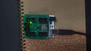
| La carte-mère soudée mais pas encore programmée |
|---|
Carte RNDIS
NOTES
deux ports USB pour la carte fille : un pour la connexion en ISP/Réseau à l'ordinateur et un pour la programmation. Possibilité de faire une connexion SPI avec un câble RJ45

