SE4Binome2024-1
Lien git : https://gitea.plil.fr/lgrevin/PICO_Binome1.git
Réalisation d'un shield arduino
Nous avons réalisé un bouclier pour Arduino Uno afin d'implémenter un système d'ordonnancement, ce qui nous permettra de simuler le fonctionnement d'une carte mère.
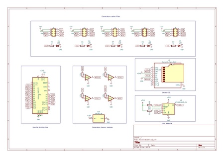
Ce bouclier est conçu pour connecter jusqu’à 5 périphériques SPI via des connecteurs IDC HE10 (8 broches), en intégrant des lignes spécifiques pour la réinitialisation et l’interruption de chaque périphérique, assurant ainsi un contrôle optimal.
En plus des connexions SPI, le bouclier comprend également une mémoire, avec deux options de stockage possibles : une carte micro-SD via un connecteur Molex 10431 ou une puce mémoire AT45DB641E, laissant la flexibilité de choisir celle qui sera soudée selon les besoins. Un convertisseur de niveau (74LV125) est également intégré pour assurer la compatibilité de tension entre l’Arduino (5V) et les mémoires (3,3V), garantissant une communication stable entre les composants.
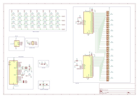
Schématique et Routage

Shield Brasé


Vérification des Leds et de la Carte SD
Code Arduino pour vérifier si les Leds fonctionnent :
https://gitea.plil.fr/lgrevin/PICO_Binome1/src/branch/main/VerificationArduino/verif.c
Nous avons écris un petit programme Arduino pour allumer les leds alternativement et donc vérifier leurs fonctionnement.
Vérification de la détection de la carte SD :
Nous avons rencontré des difficultés pour détecter la carte SD. Nous avons essayé plusieurs solutions, notamment en vérifiant l’horloge de notre Shield. Pour cela, nous avons soudé des fils aux ports GND et SCK de la puce mémoire et envoyé un code SPI à l’Arduino pour analyser le signal à l’oscilloscope, mais cela n’a pas permis d’identifier le problème. Après avoir revérifié les soudures et repassé le fer à souder sur plusieurs connexions, nous avons finalement découvert qu’une résistance mal soudée était la source du problème.
/*
SD card test
This example shows how use the utility libraries on which the
SD library is based in order to get info about your SD card.
Very useful for testing a card when you're not sure whether its working or not.
Pin numbers reflect the default SPI pins for Uno and Nano models.
The circuit:
SD card attached to SPI bus as follows:
** SDO - pin 11 on Arduino Uno/Duemilanove/Diecimila
** SDI - pin 12 on Arduino Uno/Duemilanove/Diecimila
** CLK - pin 13 on Arduino Uno/Duemilanove/Diecimila
** CS - depends on your SD card shield or module.
Pin 10 used here for consistency with other Arduino examples
created 28 Mar 2011
by Limor Fried
modified 24 July 2020
by Tom Igoe
*/
// include the SD library:
#include <SPI.h>
#include <SD.h>
// set up variables using the SD utility library functions:
Sd2Card card;
SdVolume volume;
SdFile root;
// change this to match your SD shield or module;
// Default SPI on Uno and Nano: pin 10
// Arduino Ethernet shield: pin 4
// Adafruit SD shields and modules: pin 10
// Sparkfun SD shield: pin 8
// MKR Zero SD: SDCARD_SS_PIN
const int chipSelect = 10;
void setup() {
// Open serial communications and wait for port to open:
Serial.begin(9600);
while (!Serial) {
; // wait for serial port to connect. Needed for native USB port only
}
Serial.print("\nInitializing SD card...");
// we'll use the initialization code from the utility libraries
// since we're just testing if the card is working!
if (!card.init(SPI_HALF_SPEED, chipSelect)) {
Serial.println("initialization failed. Things to check:");
Serial.println("* is a card inserted?");
Serial.println("* is your wiring correct?");
Serial.println("* did you change the chipSelect pin to match your shield or module?");
Serial.println("Note: press reset button on the board and reopen this Serial Monitor after fixing your issue!");
while (1);
} else {
Serial.println("Wiring is correct and a card is present.");
}
// print the type of card
Serial.println();
Serial.print("Card type: ");
switch (card.type()) {
case SD_CARD_TYPE_SD1:
Serial.println("SD1");
break;
case SD_CARD_TYPE_SD2:
Serial.println("SD2");
break;
case SD_CARD_TYPE_SDHC:
Serial.println("SDHC");
break;
default:
Serial.println("Unknown");
}
// Now we will try to open the 'volume'/'partition' - it should be FAT16 or FAT32
if (!volume.init(card)) {
Serial.println("Could not find FAT16/FAT32 partition.\nMake sure you've formatted the card");
while (1);
}
Serial.print("Clusters: ");
Serial.println(volume.clusterCount());
Serial.print("Blocks x Cluster: ");
Serial.println(volume.blocksPerCluster());
Serial.print("Total Blocks: ");
Serial.println(volume.blocksPerCluster() * volume.clusterCount());
Serial.println();
// print the type and size of the first FAT-type volume
uint32_t volumesize;
Serial.print("Volume type is: FAT");
Serial.println(volume.fatType(), DEC);
volumesize = volume.blocksPerCluster(); // clusters are collections of blocks
volumesize *= volume.clusterCount(); // we'll have a lot of clusters
volumesize /= 2; // SD card blocks are always 512 bytes (2 blocks are 1 KB)
Serial.print("Volume size (KB): ");
Serial.println(volumesize);
Serial.print("Volume size (MB): ");
volumesize /= 1024;
Serial.println(volumesize);
Serial.print("Volume size (GB): ");
Serial.println((float)volumesize / 1024.0);
Serial.println("\nFiles found on the card (name, date and size in bytes): ");
root.openRoot(volume);
// list all files in the card with date and size
root.ls(LS_R | LS_DATE | LS_SIZE);
root.close();
}
void loop(void) {
}

Code ordonnanceur
Un ordonnanceur sert à gérer l'exécution des tâches dans un système temps réel, en assurant qu'elles s'exécutent dans un ordre optimal et respectent les délais. Cela garantit que les processus critiques reçoivent les ressources nécessaires pour fonctionner sans interruption, optimisant la performance et la réactivité du système.
https://gitea.plil.fr/lgrevin/PICO_Binome1/src/branch/main/Ordonnanceur
Réalisation d'une carte clavier
Nous avons choisi de faire une matrice de touche pour réaliser la carte clavier.
Cette matrice contient 8 colonnes et 4 lignes soit un total de 32 boutons. Nous avons également choisi d'ajouter des leds RGB une sur chaque ligne et chaque colonne
Datasheet des LEDs RGB:
https://docs.rs-online.com/988a/0900766b80e2903e.pdf
Consommation de la carte clavier
La Puissance totale maximale est de 1.735W.
Schématique & Routage